fpga dev tools quartus® prime software pro
4334 Topics
Does Altera provide 3D mechanical models for device packages?
Description 3D Package Step (STP) models are available for Agilex® FPGA devices. They are included in the Compact Thermal Models that are available to customers with “My Collateral” secure content entitlement. Resolution To request “My Collateral” entitlement, visit your My Altera dashboard and request “My Collateral” access. A on-line Non-disclosure agreement is required.264Views0likes0Comments
Why does Linux fail to access QSPI flash components across all supported devices in the QPDS26.1.1_REL_GSRD_PR release?
Description Due to the change in the default value (from ‘n' to 'y’) of the CONFIG_MTD_SPI_NOR_USE_4K_SECTORS config in Linux from QPDS26.1.1_REL_GSRD_PR release and onwards, Linux may fail to access components from the QSPI flash device if the component was built with a configuration using an erase sector size of 64KB. This may be the case for loading the Linux file system (with jffs or ubi format), which is normally built for a QSPI erase sector size of 64 KB in Altera binary build recipes. This problem may be observed in any of the Altera SoC devices. Resolution To work around this problem, you need to change the value of the CONFIG_MTD_SPI_NOR_USE_4K_SECTORS config to 'n'. You can do this by adding this line to the arch/arm64/configs/defconfig file: CONFIG_MTD_SPI_NOR_USE_4K_SECTORS=n You can also override the value of this config as shown next: git clone -b QPDS26.1.1_REL_GSRD_PR GitHub - altera-fpga/linux-socfpga: Linux development repository for socfpga cd linux-socfpga cat << EOF > config-fragment-agilex5 CONFIG_MTD_SPI_NOR_USE_4K_SECTORS=n EOF make defconfig ./scripts/kconfig/merge_config.sh -O ./ ./.config ./config-fragment-agilex5 <continue here the regular Linux build> It is not expected that this problem will be fixed in a future release, as the community rejected changing the CONFIG_MTD_SPI_NOR_USE_4K_SECTORS config to 'n'.125Views0likes0CommentsWhy I can't change the device family in Power and Thermal Analyzer?
Description Due to a problem in the Quartus® Prime Pro Edition Software version 26.1, you may not be able to change to a different device family in Power and Thermal Analyzer (PTA) after you create or open a design. For example, if you open a design targeting a Stratix® 10 device, you may not be able to change to an Agilex® FPGA device. In version 26.1, if you select File > New File to create a new PTA design, the new file wizard does not appear. Without the wizard, you cannot select a different device family when creating a new file. Resolution PTA locks a design to the device family selected when the file is created. To explore power consumption across different device families, create a new PTA file in the target family and import your existing design. To import an existing PTA design into a different device family: Create a new PTA file targeting the desired device family. Use the Import function to bring your existing PTA design into the new file. If you chose the wrong device family when creating a file, close the existing file and create a new one. In the File menu, select New File, and select the correct device family in the new file wizard. In version 26.1 of Power and Thermal Analyzer, the new file wizard does not appear when you select New File. To work around this issue, exit and restart PTA. After restarting, select File > New File to open the new file wizard and select the correct device family.486Views2likes0CommentsWhy does Quartus® Prime Pro give an error when trying to route HPS reset signals, such as s2f_rst or s2f_cold_rst, to the Fabric using the localized Sector Clock Network?
Description Due to device architecture requirements in Altera® SoC FPGA families with a Hard Processor System (HPS), the Quartus® Prime Pro Edition Software version 25.3.1 reports a fitter routing error when you try to route certain HPS-to-FPGA reset signals to the FPGA fabric using the localized Sector Clock Network instead of the Global Clock Network. In the Agilex® FPGA architecture, there is a device-wide Global Clock Network (meant for high fan-out signals) and a localized Sector Clock Network (meant for low fan-out, smaller regional scope, or localized logic structures). Certain signals, such as s2f_rst or s2f_cold_rst, are restricted to be only on the Global Clock Network. For example, if you use: set_instance_assignment -name GLOBAL_SIGNAL OFF -to ...|hps_inst|s2f_cold_rst Quartus reports an error similar to: Error (170084): Can't route signal "...|hps_inst|s2f_cold_rst" to atom ... Resolution Certain signals, such as s2f_rst or s2f_cold_rst, are restricted to be only on the Global Clock Network. To work around this routing error in the Quartus® Prime Pro Edition Software: Remove any instance assignment that sets GLOBAL_SIGNAL to OFF for HPS-to-FPGA reset outputs (for example, s2f_rst or s2f_cold_rst). Recompile the design and allow Quartus to route these reset signals on the Global Clock Network. This behavior reflects device architecture and fitter rules; it is not scheduled to be changed to allow HPS-to-FPGA reset signals on the Sector Clock Network.51Views0likes0CommentsWhy Can't I Program Using Active Serial Programming with my USB Blaster III?
Description Due to a firmware issue the USB Blaster III Development cable may not have the correct product ID and may inadvertently disabled FLASH programming using the active serial x1/x2 interface in the Quartus Programmer. It does not impact just using ASx4 to program your FPGA or using JTAG to program your flash device. Is my Development Cable affected by this? If your USB Blaster III Development cable has a serial number ranging from UB3000000 - UB3006090, then you will need to update the PID. Resolution To resolve this issue the Product ID of the cable should be updated to (6023). Perform the following steps on Windows to update the ID. Download and Install the FT_PROG.exe the EEPROM Programming Utility from FTDI https://ftdichip.com/utilities/ Plug-in your USB Blaster III development cable into your computer. Uninstall the USB Blaster III device driver from the device manager. Open the Windows Device Manager. Find the group called JTAG cables, under this group there should be a USB Blaster III device. Right Click on the USB Blaster III device and Click Uninstall. Tick "Attempt to delete the driver for this device" or "Delete the driver software for this device" during uninstallation. This prevents the UB3 driver from being automatically reinstalled. Install the FTDI Device driver. Open the Windows Device Manager. Find the group called Other Devices. In the group Other Devices there may be several USB Blaster III devices. To Identify the correct USB Blaster III device Right click on each USB Blaster III device and click Properties. Find USB Blaster III device that contains values that end with MI_00 Once Identified, Right click on correct USB Blaster III device and click Update driver To Update driver click Browse my computer for drivers Search and select the USB Blaster III driver directory under your Quartus installation. <Quartus Path>\qdrivers\quartus\drivers\usb-blaster-iii Click Let me pick from a list of available drivers on my computer. If, Select your device’s type from the list below, choose Universal Serial Bus controllers. When selecting a driver click the FTDI manufacturer then select USB Serial Converter A Version: 2.12.36.4 and click the Next button. Program your USB Blaster III Development Cable with FT_PROG.exe to update your product ID. Open the FT_PROG.exe from FTDI installed in step 1. From the DEVICES menu click Scan and Parse to bring up your USB Blaster III Device Under the Device Tree select the section called USB Device Descriptor This should contain a property called Product ID and should have a value of 6023, change this to 6023 if it is not set to this value. Once changed, under the DEVICES menu click Program to flash the EEPROM Uninstall the FTDI driver installed in step 4. Open the Windows Device Manager. Find the group Universal Serial Sub controllers In the Universal Serial Bus controllers right click on the USB Serial Converter A and Click Uninstall. Do not tick "Attempt to delete the driver for this device" or "Delete the driver software for this device". Re-Install the USB Blaster III device driver. Open the Windows Device Manager. Find the group called Other Devices. In the group Other Devices there may be several USB Serial Port devices or USB Blaster III devices. To Identify the correct USB Serial Port device Right click on each USB Serial Port device and click Properties. Find USB Serial Port device that contains values that end with MI_00 Once Identified, Right click on correct USB Blaster III device and click Update driver To Update driver click Browse my computer for drivers Search and select the USB Blaster III driver directory under your Quartus installation. <Quartus Path>\qdrivers\quartus\drivers\usb-blaster-iii Click the Next button. Windows should show USB Blaster III driver installed. Verify USB Blaster III device has the correct Product ID. Open the Windows Device Manager. Find the group called JTAG cables, under this group there should be a USB Blaster III device. Right click on each USB Blaster III device and click Properties. Values should contain PID_6023 in the string, if not unplug and re-plugin the device. Open Quartus Programmer and Validate that the Active Serial programing is now available.531Views0likes0CommentsWhy does the SystemConsole.refreshMasters DSP Builder function fail?
Description When using the SystemConsole.refreshMasters DSP Builder function in the Quartus® Prime Pro Edition version 26.1.1 and above, you may see the following error: Unable to resolve the name 'com.altera.systemconsole.matlabapi.SystemConsoleLink' This error occurs because the Java version used by MATLAB is incompatible with com.altera.systemconsole.matlabapi.SystemConsoleLink. For DSP Builder version 26.1.1 and later, MATLAB must use Java version 11 or later for SystemConsole.refreshMasters to run successfully. Resolution You can change MATLAB's Java version using either the jenv MATLAB function or the matlab_jenv executable. For information on how to use jenv and matlab_jenv, refer to the MATLAB documentation.38Views0likes0CommentsWhy does Quartus® Prime Pro report Error (26193) and a Fatal Error in ddm_module_iters.cpp during Synthesis for F-Tile designs with secure MIFs?
Description Due to a problem in the Quartus® Prime Pro Edition Software version 26.1.1, Synthesis may fail on Agilex® 7 FPGA F-Tile designs that use secure Memory Initialization Files (MIFs) when hierarchy paths contain period (.) characters introduced by RTL generate blocks. The Quartus® Prime Pro Edition Software incorrectly treats periods inside generate-block instance names as hierarchy separators. As a result, the tool cannot resolve the secure MIF hierarchy path, reports Error (26193), and then terminates with a fatal assertion. Resolution To fix this problem in the Quartus® Prime Pro Edition Software version 26.1.1, install patch 1.03 below for the correct OS. This problem is scheduled to be fixed in a future release of the Quartus® Prime Pro Edition Software.145Views0likes0CommentsError: The “…/script/../niosv_software/dp_demo_bsp/settings.bsp file does not exist
Description Due to a problem in the Quartus ® Prime Pro Edition Software version 26.1, the generated DisplayPort example design for Stratix® 10 FPGA does not contain the correct BSP file. The command “quartus_py .\build_niosv_sw.py -d” mentioned in DisplayPort Stratix® 10 FPGA IP Design Example User Guide does not regenerate correct BSP file either, which causes the error “Error: The “…/script/../niosv_software/dp_demo_bsp/settings.bsp" file does not exist”. Resolution To fix this problem, execute “quartus_py ./build_niosv_sw.py -d -b” instead to regenerate .elf file. The “-b” option is only necessary for the first run.105Views0likes0CommentsWhy are there no example design options available in the “Select Design” drop-down list in the DisplayPort IP Parameter Editor GUI?
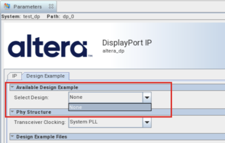
Description Due to a problem in the Quartus ® Prime Pro Edition Software version 26.1, the drop-down list for “Select Design” in the Display Port IP Parameter Editor GUI only has “None” option, as shown in the screenshot below. Resolution This problem has been fixed beginning with version 26.1.1 of the Quartus® Prime Pro Edition Software.165Views0likes0CommentsError: (vlog-7) Failed to open design unit file
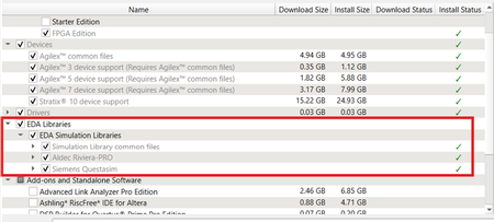
Description Due to simulation models not being installed along with the Quartus ® Prime Pro Edition Software, an error such as: Error: (vlog-7) Failed to open design unit file "C:/altera_pro/26.1.1/quartus/eda/sim_lib/220model.v" in read mode may occur during simulation. The root cause of missing files is that “EDA libraries” are not installed properly during installation of the Quartus ® Prime Pro Edition Software. Resolution To fix this problem, make sure “EDA Libraries” has been checked and installed properly during installation of the Quartus ® Prime Pro Edition Software, as shown in the screenshot below.93Views0likes0Comments